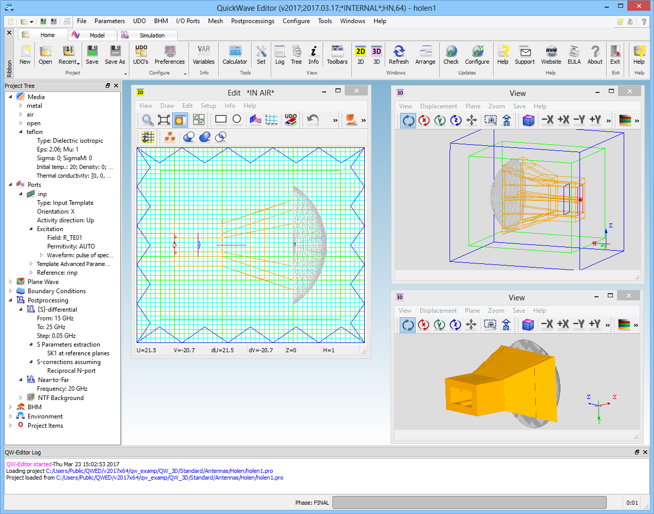
QuickWave Editor
Project structure, simulation parameters and FDTD mesh definition.
QuickWave Editor (QW-Editor)
permits graphical definition of project structures, mesh generation, and specification of simulation parameters via a convenient system of dialogue boxes.
In QW-Editor, shape and filling of arbitrary 3D and V2D circuits can be defined by picking up parameterised objects from object libraries. Moreover, the user can create his own objects by writing scripts in a simple UDO language. Manual operation with mouse and keyboard is also possible. QW-Editor provides an intuitive user interface with convenient dialogues, menu commands, and ribbon and toolbar buttons.
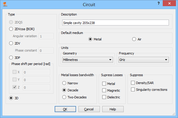
Project Settings
The following choices are available for geometrical units:
- metres [m]
- millimetres [mm]
- microns [um]
- nanometres [nm]
- inches [inch]
- mils [mils]
The following choices are available for frequency units:
- petahertz [PHz]
- terahertz [THz]
- gigahertz [GHz]
- megahertz [MHz]
- kilohertz [kHz]
- hertz [Hz]
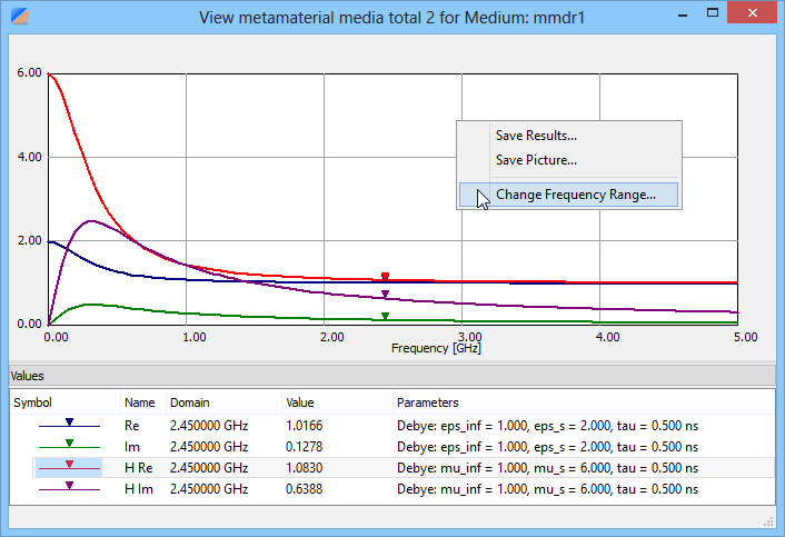
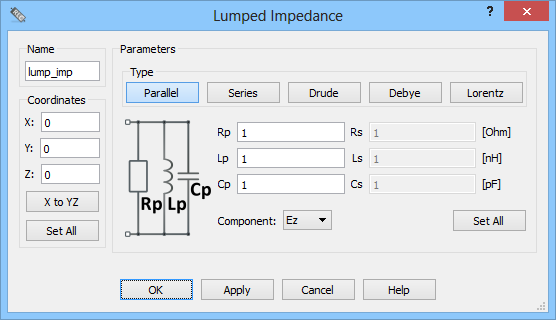
Materials
QuickWave software supports the following media types:
- PEC
- PMC
- Metallic
- Dielectric Isotropic
- Dielectric Anisotropic
- Dielectric Dispersive
- Dielectric Dispersive Anisotropic
- Dielectric Dispersive Nonlinear
- Cold Plasma
- Metamaterial
- Ferrite
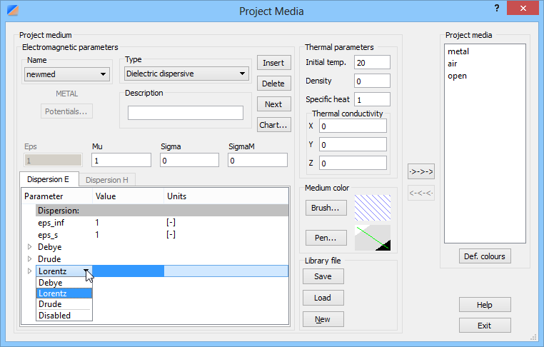
See also online documentation about materials.
Geometry
More or less complicated shapes have been created using the library UDOs or their combinations. Drawing using UDO scripts is the best way to introduce complicated geometries. The UDO Library contains over 500 parametrised and ready to use UDO scripts grouped into categories focusing on particular applications.
Moreover, some practice with manual software operation can be helpful in both preparation of new UDOs and verification of their correctness.
The geometry can be also imported (the UDO script will be produced) from:
- *.dxf file with DXF Converter
- *.sat file with SAT Filter optional module
See also online documentation about geometry.
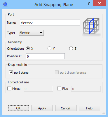
I/O Ports
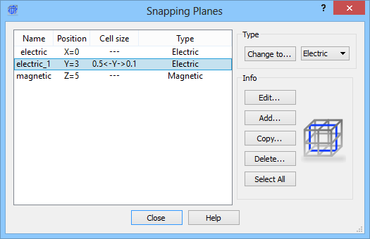
The I/O ports, Mesh Snapping Planes, Absorbing Boundary Conditions and NTF can be introduced in a manual way or using special UDOs available in the UDO library.
The more convenient way of introducing the I/O ports using a set of dedicated dialogues.
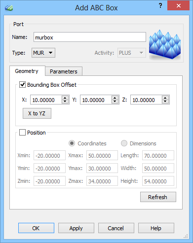
See also online documentation about I/O ports.
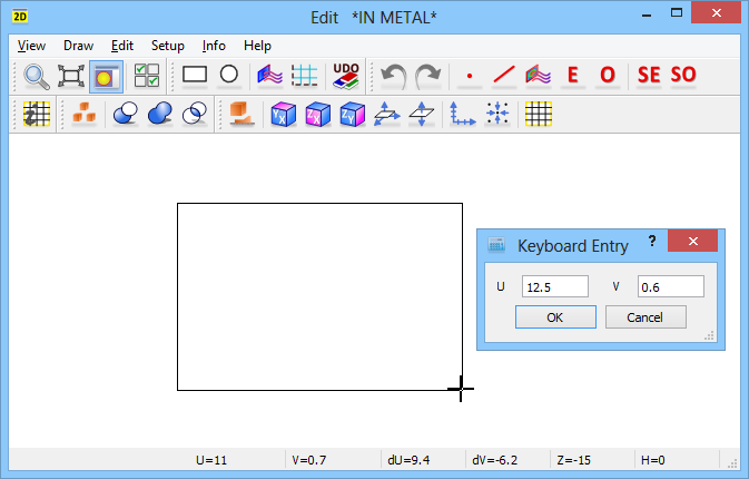
FDTD Mesh
Mesh refers to the set of FDTD cells. These cells of cubicoidal (or cubicoidal cut by a plane) shape have the basic size defined through the Mesh Parameters dialogue. However, the actual cell size may be modified downwards by the software to fill the area between mesh snapping planes with an integer number of cells. Mesh snapping planes are either introduced explicitly by the user or forced automatically by the QW-Editor (for example, at horizontal boundaries of metal elements).
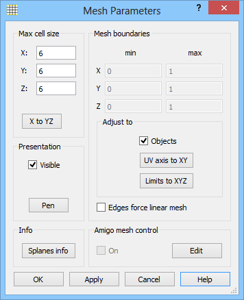
See also online documentation about FDTD mesh.
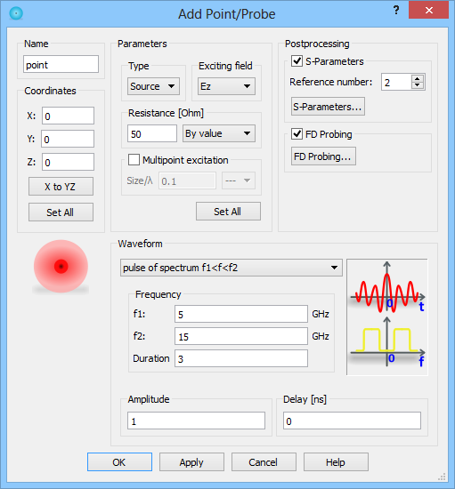
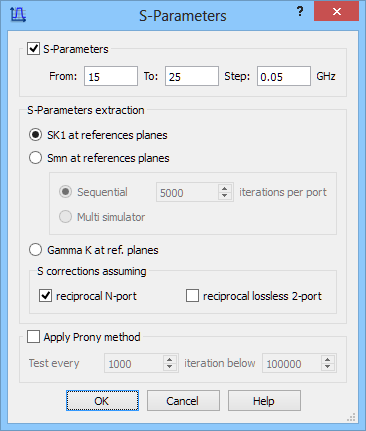
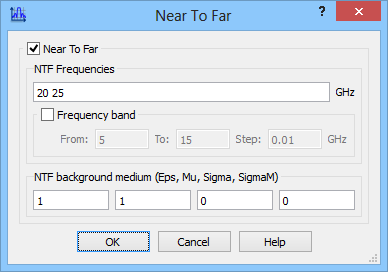
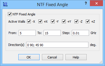
Post-processings
Time-domain data, such as time evolution of fields or currents and voltages at lumped ports, can be accessed in QW-Simulator at any time and any location within the structure. Data in the frequency domain, such as S-Parameters, are produced by means of the Fourier transform, which must be performed on selected time-domain quantities throughout the simulation. Additional memory must also be allocated at the beginning of the simulation process. For these reasons, the user must indicate the required frequency domain results before starting QW-Simulator.
The following post-processings are available in QuickWave:
- S-Parameters
- S-Parameters using QProny module
- FD-Probing
- Power Available
- Near To Far
- NTF Fixed Angle
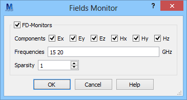
- FD-Monitors
- ExH Time Integral
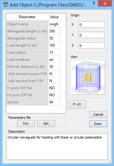
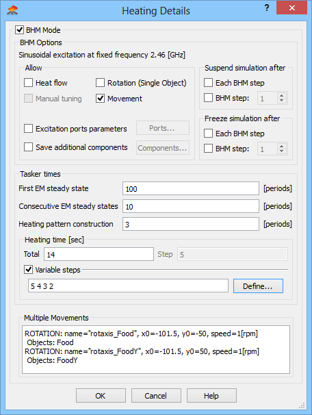
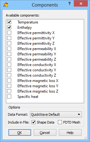
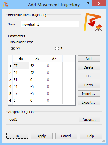
Basic Heating Module
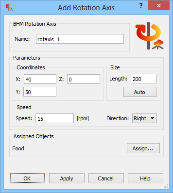
Basic Heating Module allows for microwave heating analysis including loads rotation and translation, frequency tuning, heat flow and material parameters modification as a function of dissipated power.
The software has been prepared to work in sophisticated regimes, modelling rotation and movement of the heated load(s) even along complicated trajectories, etc.
UDO Scripts
QW-Editor includes QW-ObjectGenerator. QW-ObjectGenerator is essentially an interpreter for source scripts provided by QWED in a form of library UDOs or prepared by the user in a specially developed UDO (User Defined Object) language. These source programs are stored in files with *.udo extension. The UDO language is simple and yet gives the user the possibility to create his own arbitrarily complicated parametric objects, best suited for his particular requirements.
There are three basic advantages of application of parameterised objects in electromagnetic design:
- In the vast majority of applications engineers design structures, which can be composed of typical primitive objects by simple putting them in proper place or by exercising Boolean operations on them.
- In many practical cases design engineers deal with one type of a microwave structure for a long time. Not changing the general shape, they modify its dimensions to optimise performance or to redesign the device for a different set of parameters or a different frequency band. In such a case the most convenient way to proceed is to define the investigated structure as User Defined Object or as a set of such objects with some dimensions introduced as parameters. To change one of these dimensions it will be sufficient to call the object once more and to introduce new values of the parameters - the operation which can be accomplished in seconds.
- Parameterized UDOs open new horizons for running QW-3D in an automatic optimisation loop using QW-OptimiserPlus, the old QW-Optimiser or other external optimisers like for example those available in MATLAB TOOLKIT.
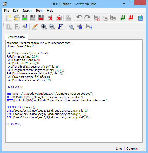
See also online documentation about UDO scripts.
UDO Scripts Library
