Co-processings & post-processings
Co-processings
QuickWave is very flexible in so called co-processings. The user can open arbitrary number of windows for display of field components, dissipated power, Poynting vector etc. (in various graphical display systems and at any simulation stage). The decisions about the number and type of the windows showing valued deliverable form of the instantaneous filed components do not need to be taken prior to launching the simulation.
The co-processings data are available (for viewing, storing, etc.) at any simulation stage.
Display
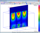
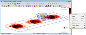
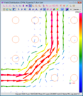
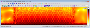
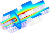
- various display types for field distribution viewing (quasi-three-dimensional, fields intensity represented by colours, vector form)
- linear and decibel scales
- automatic and manual scales
- one and two dimensional displays
- two dimensional displays available for each cells layer
- 3D presentation of the antenna radiation pattern
- 3D presentation of the field components distribution, currents, material parameters etc. using QViewer module
- instantaneous and envelope (i.e. time-maximum and time-averaged) values of the displayed component
Data
- fields (E and H field components), Poynting vector and power dissipated distribution available at any simulation stage (time domain monitoring)
- fields (E and H field components), Poynting vector and power dissipated distribution for real and imaginary grids, available for the periodic structures
- SAR calculations
- temperature and enthalpy distribution for microwave heating problems
- effective media parameters distribution
- watching field components along a specified line in space/versus time/along pre-defined contour
- virtual measurements of attenuation and SWR
- Time-Domain Reflectometry results (with virtual measurements of reflection coefficient and location of the discontinuity)
- power dissipated and energy stored in electric and magnetic field, and the resultant Q-factor calculations (also for real and imaginary grids for periodic structures)
- power dissipated and stored energy calculations for the entire lossy volume or in the specified objects
- energy dissipated over the entire duration of a pulse of limited duration (power dissipated integration in time)

Post-processings
Here the tasks requiring calculation of the Fourier transformation of fields (S-parameters, radiation patterns or field distribution of a particular frequency extracted from pulse excitations) are included. In this case an apriori knowledge about the data to be accumulated during simulations is required (user chooses data that should be calculated before running the simulation).
All the post-processing data can be viewed, stored, etc., at any simulation stage.
Display
- linear, decibel, and quadratic (for S-parameters, radiation and scattering patterns) scales
- automatic and manual scales
- Smith and polar chart
- loading reference results for S-parameters, radiation and scattering patterns
S-parameters
- broadband S-parameters extraction (results available at any simulation stage)
- full S-parameters matrix calculations (exciting the consecutive ports in sequential or multi-simulator regimes)
- reciprocity option available for S-parameters calculation
- reflection coefficient calculations for several ports simultaneously, during a single simulation run (applicable for multi-source networks when N sources operate simultaneously, and consequently the S-matrix cannot be calculated)
- virtual shift of the reference plane (the plane where the S-parameters extraction is performed)
- frequency dependent wave impedance (reference impedance for S-parameters calculations) and propagation coefficient of transmission lines
- power balance calculation
- standing wave ratio (SWR) and group delay calculations
- S-parameters embedding and deembedding
Radiation and scaterring
- antenna radiation patterns and scattering patterns of a scattering structures for wide angle range, at multiple frequencies, for any plane
- gain (directive, power, absolute, relative, fields scaled to 1m), radiation efficiency, radiation resistance and radiated power calculations
- radiation patterns for linear and circular polarisation
- radiation patterns for antenna arrays
- radiation pattern at a chosen near-to-far transformation (Huygens) surface
- far field 3D radiation patterns calculations
- radiation pattern calculations in an arbitrary isotropic medium
- radiation patterns for a specified directions versus frequency
- impulse response in the far-field
Lumped
- Fourier transforms of terminal voltage across/current through resistor at any circuit point
- Fourier transforms of field integrals along defined contours
- power available from the source calculations (Fourier transform of the excitation waveform)
- energy available from the source
Fields
- monitoring the field distribution at multiple frequencies in one simulation (frequency domain monitoring) with a sparsity factor in space and time
- animation of the time domain field distribution (at chosen frequencies) for frequency domain monitoring
- time integration of the Poynting vector